From Electrons to Applications: The OSI Model Explained Like Never Before
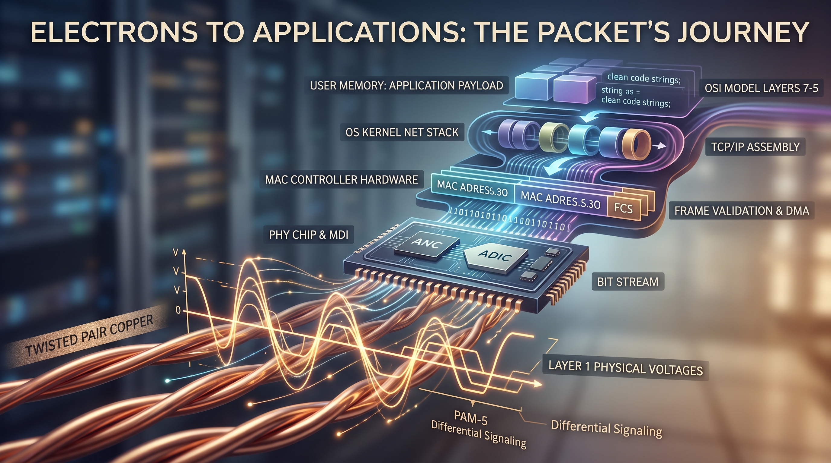
We treat modern network connectivity like a flawless magic trick: an API call fires, a database queries, and a dashboard populates in milliseconds. But beneath the clean, high-level abstractions of modern software lies a brutal, high-speed collision of physics and silicon. Every single payload traversing an enterprise datacenter or a local gateway must eventually strip away its software elegance and translate itself into raw electrical energy. The reality of networking isn't just code; it is a chaotic environment of microscopic voltage fluctuations, differential signaling, and electromagnetic waves racing across twisted copper pairs at a fraction of the speed of light.
The journey of a packet from these analog electrical pulses back into a perfectly ordered application payload is an absolute masterclass in engineering. It is a microscopic, high-stakes relay race where physical PHY chips, hardware MAC controllers, Direct Memory Access (DMA) engines, and operating system kernels must orchestrate the handoff of data in billionths of a second to prevent the total collapse of communication. This is the true story of the OSI model, unmasked and in motion—a granular, step-by-step breakdown of exactly how a network interface card rips raw voltage off a wire and resurrects it into the digital world.
The Packet's Descent: From Application Memory to Copper Voltage
When an application sends data across a network, it doesn't just throw raw bytes onto a wire. Instead, it initiates a heavily orchestrated downward journey across the OSI model. Data undergoes encapsulation—each layer wrapping the payload with its own control headers, slicing it into manageable chunks, handing it to the kernel, crossing the PCIe bus, and finally converting it into electrical voltages that propagate across copper pairs.
This multi-part technical guide breaks down that exact descent, starting from user space down to the physical medium.
Part 1: The Upper Layers (OSI Layers 7 to 5) — From User Intent to Structured Bytes#
The journey begins in User Space, far away from hardware. When an application (such as a web browser or a database client) wants to communicate, it creates data in human- or software-readable formats.
Layer 7 (Application): This is where user intent is translated into application-layer protocols (HTTP, TLS, DNS, SSH). For instance, an HTTP client constructs a GET request string:
GET /index.html HTTP/1.1.Layer 6 (Presentation): Responsible for data syntax, serialization, and security. If encryption is enabled (like TLS 1.3), the presentation layer serializes the application data, encrypts the plaintext payload into ciphertexts, and adds its own record headers.
Layer 5 (Session): Establishes, maintains, and terminates communication sessions between applications, keeping long-lived data exchanges distinct and synchronized.
Once formatted, the application triggers a system call (like write() or send()) to hand the payload over to the operating system's kernel.
Part 2: The Transport Layer (OSI Layer 4) — Slices, Streams, and Reliability#
At the Transport layer, the operating system's network stack takes the raw application data and decides how it should be delivered. The two primary mechanisms here are TCP and UDP.
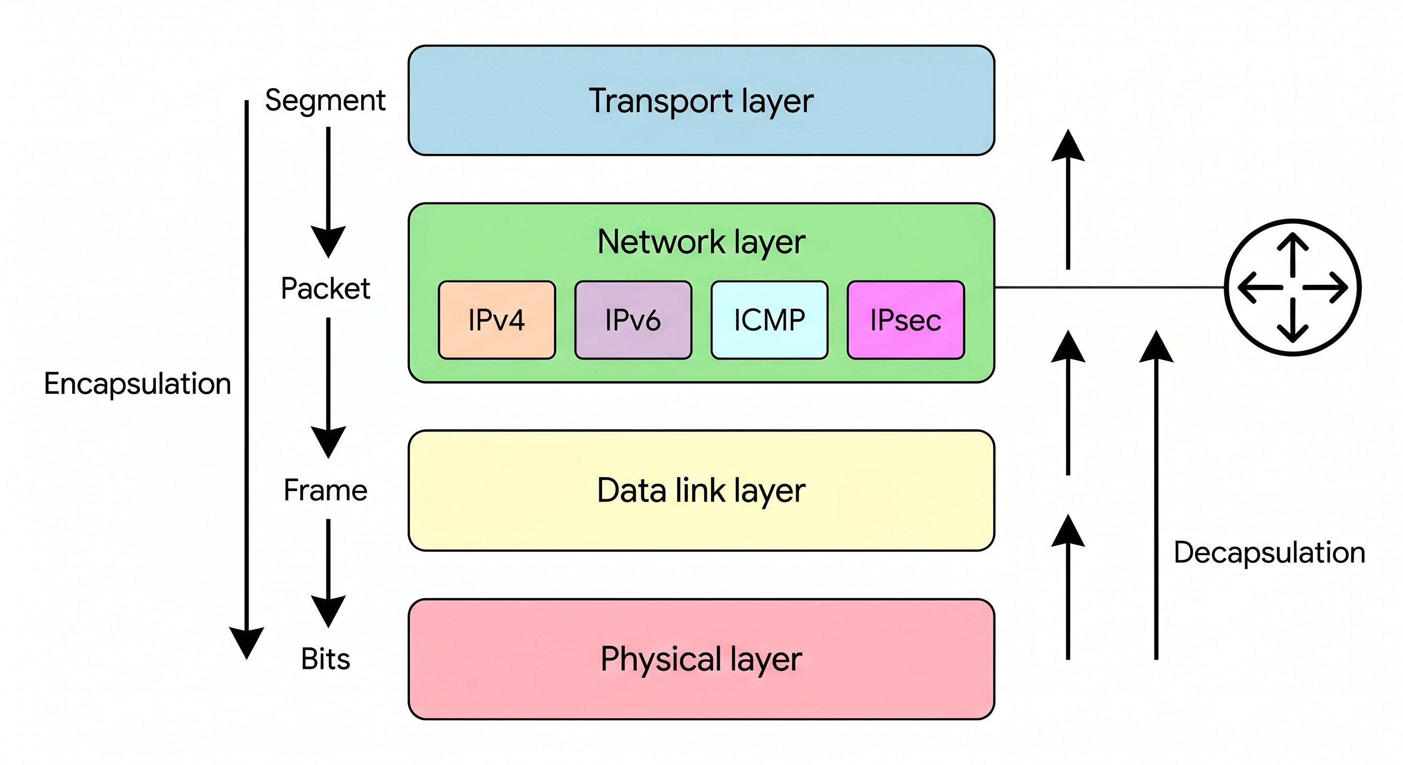
The OSI Encapsulation Descent. Source: edu-search-genmedia
TCP vs. UDP Encapsulation#
TCP (Transmission Control Protocol): If reliability is required, the kernel breaks the continuous byte stream into segments that fit within the MSS (Maximum Segment Size). It appends a 20-to-60 byte TCP header containing source/destination ports, sequence numbers for reassembly, acknowledgment numbers, window sizes for flow control, and checksums.
UDP (User Datagram Protocol): For lightweight, low-latency traffic, the kernel wraps the payload in a compact 8-byte UDP header containing just ports, length, and a checksum.
Once encapsulated into a segment, the transport layer hands the data down to the Network layer via internal kernel structures (such as sk_buff in Linux).
Part 3: The Network Layer (OSI Layer 3) — Routing, Addressing, and Packetization#
The Network layer is where global routing and logical addressing happen. Here, IPv4 or IPv6 takes over.
IP Header Addition: The kernel adds a 20-byte (IPv4) or 40-byte (IPv6) header containing the Source IP address, Destination IP address, Time to Live (TTL) hop limit, and protocol identifiers (e.g., indicating that the payload is TCP or UDP).
Route Lookup & MTU Check: The kernel checks its routing table to determine which local network interface (NIC) should handle the packet. It evaluates the MTU (Maximum Transmission Unit)—typically 1500 bytes for standard Ethernet. If the packet exceeds the MTU, the network layer triggers fragmentation (or relies on Path MTU Discovery).
Neighbor Resolution: Before the packet can be handed to the network card, the OS must find the physical destination address. It consults the ARP table (IPv4) or NDP cache (IPv6) to map the next-hop IP address to a physical MAC address.
Part 4: The Data Link Layer (OSI Layer 2) — Framing, MAC Addressing, and FCS#
With the logical packet ready, the OS and the Network Interface Card (NIC) driver work together at Layer 2 to turn the packet into an Ethernet Frame.
MAC Header Addition: A 14-byte Ethernet header is prepended to the packet, containing the destination MAC address, source MAC address, and an EtherType field (e.g.,
0x0800for IPv4).DMA and PCIe Handoff: The driver places the frame into a kernel memory ring buffer and instructs the NIC's DMA (Direct Memory Access) engine via the PCIe bus to pull the frame into the NIC's onboard SRAM buffer.
FCS Generation: Just before transmission, the NIC's hardware MAC controller computes a Frame Check Sequence (CRC-32) over the frame's contents and appends it to the trailer. This ensures the receiving end can detect any bit-level corruption.
Part 5: The Physical Layer & Silicon (OSI Layer 1) — From Bits to Voltage, Currents, and Copper#
The final stage shifts from software and silicon registers to pure analog physics. The NIC's PHY (Physical Layer) chip transforms the digital bitstream into physical energy on the wire.
Preamble and SFD: The physical layer prepends a 7-byte Preamble (
10101010) and a 1-byte Start Frame Delimiter (10101011) to allow the receiver's clock to synchronize with the incoming stream.Line Coding and Scrambling: Raw bits are scrambled to eliminate DC bias and ensure frequent signal transitions. For Gigabit Ethernet (1000BASE-T), bits are grouped into symbols and modulated using PAM-5 (Pulse Amplitude Modulation), mapping digital bit pairs to specific voltage tiers.
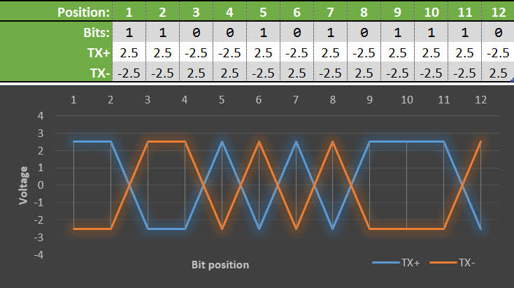
Differential Voltage Signaling Across Copper Pairs. Source: Practical Networking
Differential Signaling via MDI: The line drivers convert digital symbols into actual electrical currents across twisted copper pairs using differential signaling. Instead of referencing ground, the transmitter sends complementary voltages down two wires in a twisted pair (e.g., +2.5V on TX+ and -2.5V on TX-).
Electromagnetic Propagation: The voltage difference between the pair creates an electromagnetic wave that travels down the copper cable at roughly 60-70% the speed of light, ready to be picked up by the physical receiver on the other end of the link.
Receiving data is a race against physics and CPU cycles. When an electrical pulse hits a network interface card (NIC), hardware and software must collaborate to validate, reassemble, and deliver the payload to an application in microseconds.
Here is the exact bottom-up sequence of how a packet travels from physical copper wire into application memory.
Part 1: The Physical Layer (OSI Layer 1) — Voltage to Bits#
The journey begins on the physical medium, where electromagnetic waves propagate down twisted copper pairs. The NIC’s PHY (Physical Layer) chip captures this analog energy and translates it back into a digital bitstream.
Clock Recovery: Unlike a motherboard bus, Ethernet doesn't have a separate wire for a clock signal. The receiver's Phase-Locked Loop (PLL) hardware analyzes the incoming voltage transitions to extract the sender's clock timing and synchronize its own internal receiver.
Symbol Decoding: For Gigabit Ethernet, differential voltages (measured across the twisted pairs) arrive as PAM-5 modulated symbols. The PHY's analog-to-digital converter (ADC) reads these 5 voltage tiers and maps them back into binary code.
Descrambling and PCS: Because the sender scrambled the data to prevent long runs of identical voltages, the Physical Coding Sublayer (PCS) applies an inverse polynomial algorithm to descramble the data back into its original, raw bitstream of 1s and 0s.
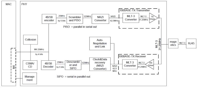
Internal Architecture of a Receiver PHY. Source: Embedded Hardware Design
Part 2: The Data Link Layer (OSI Layer 2) — Synchronization and Integrity#
The PHY passes the continuous raw bitstream to the MAC (Media Access Control) chip (often via a bus like SGMII). The MAC must find where the actual data frames start and stop.
Frame Synchronization: The MAC scans the bits for a specific pattern: 7 bytes of alternating 1s and 0s (the Preamble), followed by a Start Frame Delimiter (
10101011). This triggers the MAC to begin recording a new frame.Hardware Address Filtering: The MAC reads the destination MAC address in the Ethernet header. If it does not match the NIC's burned-in address, a broadcast address, or a subscribed multicast address, the silicon instantly discards the frame. The OS never even knows it existed.
FCS Validation: As the MAC pulls in the frame, it recalculates the CRC-32 hash. If its result does not match the 4-byte Frame Check Sequence appended to the end of the frame, the data was corrupted in transit (e.g., by electrical interference) and is silently dropped.
Part 3: The Hardware-OS Boundary — Ring Buffers and Interrupts#
Once the MAC possesses a valid Ethernet frame, it must transfer it to the host operating system's RAM.
Direct Memory Access (DMA): The NIC acts as a bus master. Using its DMA engine, it pushes the frame across the PCIe bus directly into pre-allocated memory addresses in the host RAM, known as an RX Ring Buffer.
Hardware Interrupts: After writing one or more packets, the NIC sends an interrupt (typically MSI-X) to the CPU, signaling that data is waiting.
NAPI Polling (Linux): To prevent an interrupt storm on high-speed networks, modern OS kernels disable the NIC's receive interrupts immediately after the first one. The kernel then enters a polling mode, rapidly draining packets out of the ring buffer until it is empty, at which point it re-enables interrupts.
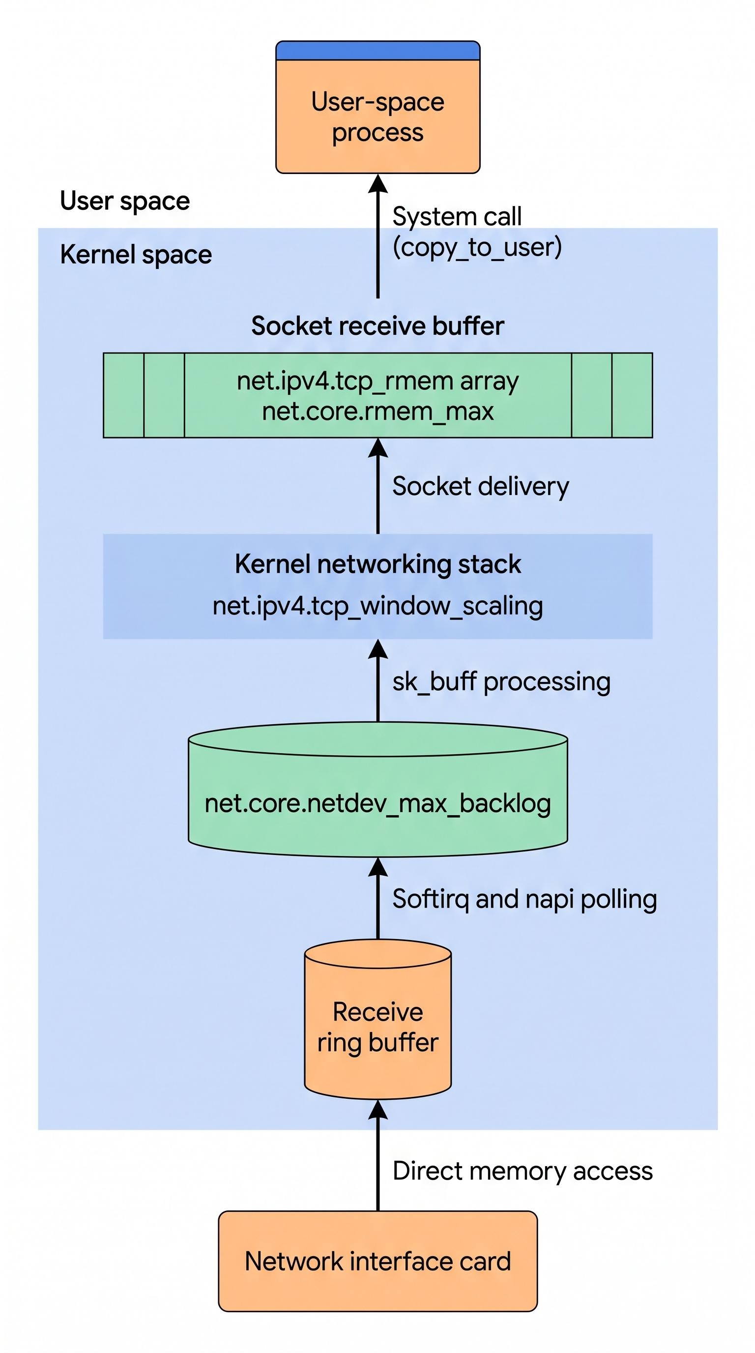
The DMA and Kernel Receive Stack. Source: edu-search-genmedia
Part 4: The Network and Transport Layers (OSI Layers 3 & 4) — Reassembly#
The device driver wraps the raw memory bytes in an OS-specific structure (like sk_buff in Linux) and passes it up the kernel's network stack for de-encapsulation.
Layer 3 (IP): The kernel strips the 14-byte Ethernet header. It inspects the IP header to ensure the Destination IP matches a local interface. (Many NICs offload the IP checksum validation in hardware).
Layer 4 (TCP/UDP): The kernel strips the IP header and examines the transport protocol.
For UDP, the packet is simply routed to the destination port.
For TCP, the kernel must look at the sequence numbers. It places the segment into a reassembly queue, ensuring bytes are ordered correctly. It also generates an ACK packet to send back to the sender. Hardware features like LRO (Large Receive Offload) can merge multiple TCP segments into one massive buffer before the kernel sees them, massively reducing CPU overhead.
Part 5: The Upper Layers (OSI Layers 5 to 7) — The User Space Handoff#
The data is now a clean, in-order byte stream sitting in kernel memory, but it still belongs to the operating system.
Socket Buffers: The kernel maps the incoming data's Destination Port (e.g., Port 443) to the specific Receive Socket Buffer owned by the target application.
Context Switch: The application, running in user space, executes a system call like
read()orrecv()(or is woken up by event notification systems likeepoll).Memory Copy and Execution: The CPU copies the payload from kernel space into the application's user space memory. The application then takes over—parsing the HTTP headers, decrypting the TLS ciphertext, or executing the database query.
Rate this article
Be the first to rate this article
Comments & Discussion0
Related articles
Between NGFW and Web Applications: Why Do We Actually Need a WAF in Production?  أمن السحابة والامتثال
Between NGFW and Web Applications: Why Do We Actually Need a WAF in Production?
A practical engineering perspective illustrating the core difference between traditional firewalls and WAFs, explaining why Layer 4 protection and NGFWs fall short in securing web applications and APIs, alongside a practical review of deployment models and false positive challenges.
Emad Al-Hadheri